
There was a scarcity of entries within the tablebot competitors shortly earlier than the registration window closed for RoboGames 2023. To verify the competition could be held, I entered a robotic. Then I needed to construct one.
What’s a tablebot?
A tablebot lives on the desk. There are three “phases” to the competitors:
- Section I: Construct a robotic that goes from one finish of a desk to the opposite and again.
- Section II: Have the robotic push a block off the ledge of the desk.
- Section III: Have the robotic push the block right into a shoebox mounted on the finish of the desk.
There may be additionally an unofficial Section IV – which is to fall off the desk and survive. I didn’t try this part.
Nearly all of tablebots are fairly easy – a few sonar or IR sensors they usually type of wander across the tabletop in hopes of finishing the totally different phases. My tablebot is decidedly totally different – and it paid off because the robotic gained the gold medal at RoboGames 2023.

Robotic construct
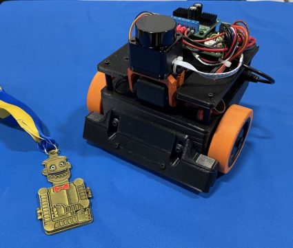
The complete robotic is constructed of 3D printed elements and random issues I had readily available.
I’ve had a type of $99 LD-06 lidars sitting round for some time, and determined this was an awesome venture to apply it to. I used a Dynamixel AX-12 servo to tilt the laser so I can discover the desk, the dice, or the objective.
All the code runs on an STM32, on my customized Etherbotix board which was designed for my Maxwell robotic various years in the past. The robotic makes use of differential drive with some 30:1 12V gear motors, which have been bought from Lynxmotion in 2008 and utilized in varied hearth preventing robots over time.
A set of small digital Sharp IR sensors are used as cliff sensors. These will be moved up or all the way down to calibrate for various desk surfaces utilizing a pair of adjustment screws. Whereas the sensors are very correct and cease the robotic, they don’t see far sufficient forward when going at full velocity, and so I additionally use the laser to detect when the desk edge is approaching.
Section 1 Software program
Section 1 is fairly straight ahead – and principally primarily based on lifeless reckoning odometry:
- The laser is angled downwards searching for the desk. That is carried out by projecting to the scan to 3D factors, and filtering out something not in entrance of the robotic at roughly desk top. When the desk disappears (variety of factors drops too low), we cut back our most velocity to one thing that’s protected for the cliff sensors to detect.
- Whereas the laser sensors search for the tip of the desk, the robotic drives ahead, and a easy suggestions loop retains the robotic centered on the desk utilizing odometry.
- When the cliff sensors ultimately set off, the robotic stops, backs up 15 centimeters, after which turns 180 levels – all utilizing lifeless reckoning odometry.
- The utmost velocity is then reset and we take off to the opposite finish of the desk with the identical habits.
Section 2 Software program
The actions of Section 2 are mainly the identical as Section 1 – we drive ahead, staying centered with odometry. The velocity is a bit decrease than Section 1 as a result of the laser can be searching for the block:
- The laser scan is projected to 3D, and we filter out any factors which might be a part of the desk primarily based on top. These remaining factors are then clustered and the clusters are analyzed for dimension.
- If a cluster is an effective candidate for the block, the robotic flip in direction of the block (utilizing, you guessed it, lifeless reckoning from odometry).
- The robotic then drives in direction of the block utilizing a easy management loop to maintain the heading.
- As soon as the block is arrived at, the robotic drives straight till a cliff sensor journeys.
- At that time, the robotic stops the wheel on the aspect of the tripped cliff sensor and drives the opposite wheel very slowly ahead in order that we align the entrance of the robotic with the sting of the desk – guaranteeing the block has been pushed off the desk.
Section 3 Software program
The ultimate part is essentially the most complicated, however not by a lot. As with the sooner phases, the robotic strikes down the desk discovering the block:
- In contrast to in Section 2, the robotic really approaches a pose simply behind the block.
- As soon as that pose has been reached, the robotic tilts the laser again to degree and finds the objective.
- The robotic then turns in direction of the objective in the identical means it first turned in direction of the block.
- The robotic then approaches the objective utilizing the identical easy management loop, and within the course of finally ends up pushing the block to the objective.
All the software program for my Tablebot is availble on GitHub.
Robogames video
Jim Dinunzio, a member of the Homebrew Robotics Membership, took a video through the precise competitors at Robogames so you possibly can really see the successful set of runs:
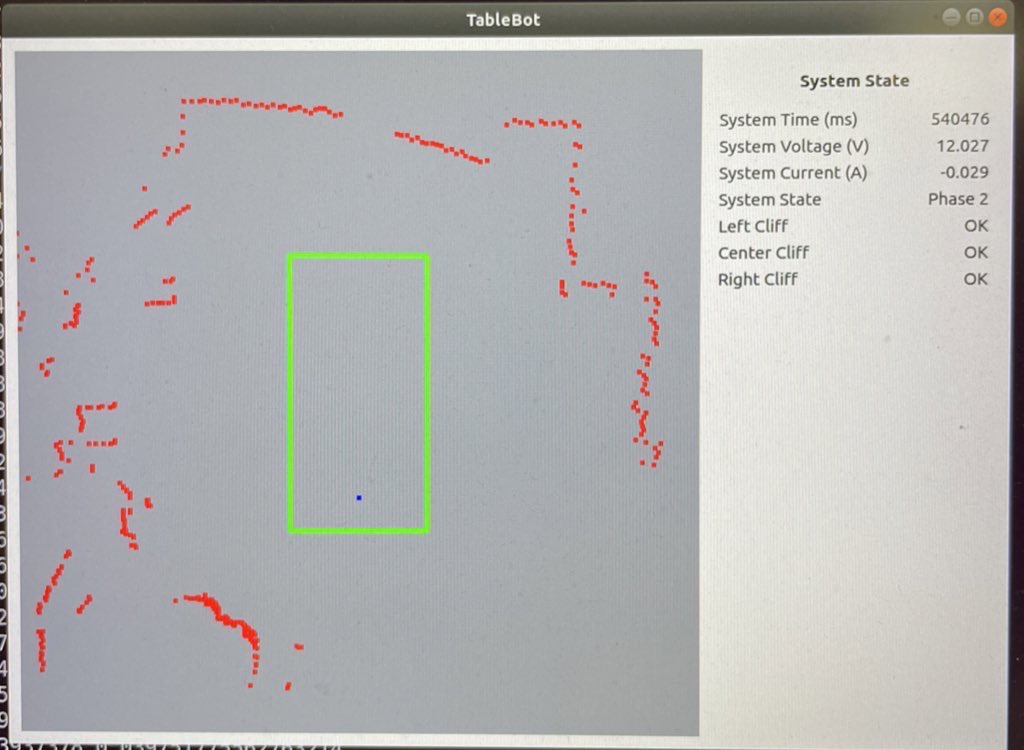
Visualization
To make growth simpler, I additionally wrote a Python GUI that renders the desk, the robotic odometry path, the laser knowledge, and detected targets and cubes.
Enjoyable with math
Alongside the best way I really ran right into a bug within the ARM CMSIS DSP library. I used the arm_sin_cos_f32() operate to compute my odometry:
arm_sin_cos_f32(system_state.pose_th * 57.2958f, &sin_th, &cos_th);
system_state.pose_x += cos_th * d;
system_state.pose_y += sin_th * d;
system_state.pose_th = angle_wrap(system_state.pose_th + dth);
This operate takes the angle (in levels!) and returns the sine and cosine of the angle utilizing a lookup desk and a few attention-grabbing interpolation. With the visualization of the robotic path, I observed the robotic odometry would sometimes bounce to the aspect and backwards – which made no sense.
Additional investigation confirmed that for very small adverse angles, arm_sin_cos_f32 returned enormous values. I dug deeper into the code and located that there are a number of totally different variations on the market:
- The model from my older STM32 library, had this explicit problem at very small adverse numbers. The identical bug was nonetheless current within the official CMSIS-DSP on the arm account.
- The model within the present STM32 library had a repair for this spot – however that repair then broke the operate for a complete quadrant!
The difficulty turned out to be fairly easy:
- The code makes use of a 512 aspect lookup desk.
- For a given angle, it has to interpolate between the earlier and subsequent entry within the desk.
- In case your angle fell between the 511th entry and the following (which might be the 0th entry resulting from wrap round) then you definitely used a random worth within the subsequent reminiscence slot to interpolate between (and to compute the interpolation). At one level, this resulted in sin(-1/512) returning outrageous values of like 30.
With that bug fastened, odometry labored flawlessly afterwards. Because it turned out, I had this identical operate/bug current in some brushless motor management code at work.
Robogames wrap up
It’s superior that RoboGames is again! This little robotic gained’t be making one other look, however I’m beginning to work on a RoboMagellan robotic for subsequent yr.

Michael Ferguson